Background
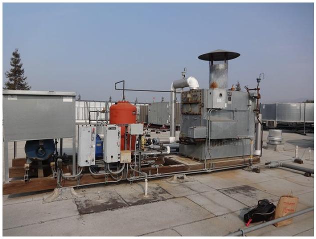
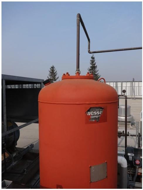
In October we discovered that the water boiler on the roof of our facility has been having aging problems for quite some time. The building maintenance crew need to go up to the roof every so often to close and open various valves in order to “reset” the system. More often than not they find out about the problem when an occupant of the building mentions or complains about the lack of hot water. So generally the maintenance person is either making a trip to the roof too early (the boiler is working just fine) just fine) or too late (people have already reported a problem). We took a look at the boiler and came upon a possible and simple test point (no plumber, natural gas engineer, electrician) required. It appeared that the air pressure tank has an externally exposed refill valve that might provide a convenient measuring point. We found out that this tank should have a normal pressure of between 10 Psi and 15 Psi. Anything below 10 or above 15 should be an alert. Using this hypothesis I built a WiFi/Cloud connected pressure sensor connected to this pressure valve.
The IoT Components
The IoT pressure sensor was made up of 3 hardware and 2 software components: MCU communication board, pressure transducer, case, MCU software, Cloud server software.
MCU Communication Board
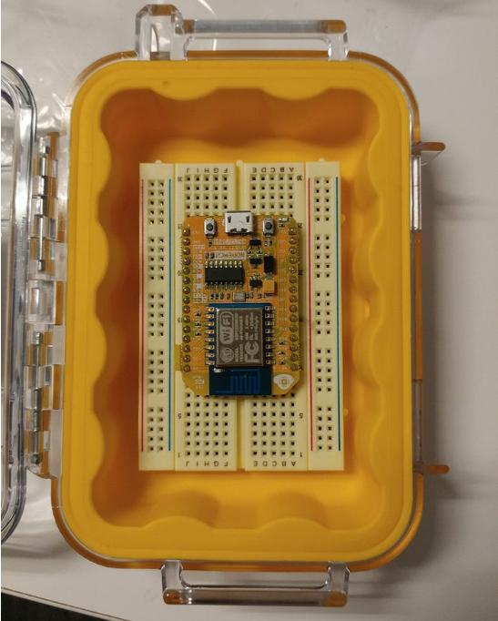
The communication board is an ESP8266 micro-controller with integrated WiFi communications and GPIO and ADC interfaces. This chip provides both logic processing and communication processing in a single package and is programmable using Arduino libraries making it easy to build a rapid prototype.

Pressure Transducer
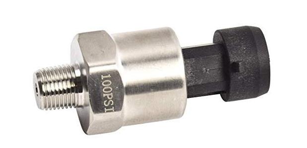
In order to measure the pressure of the air tank, I used an Autex pressure transducer. This device translates air pressure into specific voltages that can then be measured using the ADC input on the MCU board.
Case
Since the boiler is on the roof exposed to the elements and as such so would this IoT pressure sensor be exposed it was necessary to enclose the board inside a water proof enclosure. More about this later.
MCU Software
The MCU was programmed using the Arduino libraries. I was fortunate that the building WiFi had a good signal on the roof. Had it not I would either have had to look for a different communication technology (cellular) or installed a WiFi repeater to boost the signal.
The firmware starts up by connecting to the local WiFi network in the building. The board was programmed with the security credentials to allow it to access the secure building WiFi. It then requests provisioning parameters from the cloud server and then sends a “Start message” to the cloud server. Based on the parameters received from the cloud server (reporting interval, pressure high, pressure low), the firmware loops through measuring the pressure and if the pressure is out of bounds sends an alert to the cloud server. Otherwise on the programmed reporting interval the device sends the current pressure. At programmed times the firmware requests an update to the parameters. All communications are sent using HTTP GET and HTTP POST requests with the data encoded in JSON.
Cloud Sever Software
The server is a standard cloud Linux system. I wrote and installed a very small web server — about 500 lines of C code. I could have used any web server such as Apache and the CGI interface, but because this was a special purpose web interface and I wanted to experiment with a minimal design, I chose a simple single threaded web server. This would allow us to embed the necessary request/response logic inside the server itself. The code was written, though, to be compatible with the standard CGI interface of an Apache like web server. Our IoT server was then started on a separate port, so as not to interfere with the web server running on the same Linux system. The server responds to GET requests with the device’s provisioning parameters and handles POST requests storing the sensor data (time stamp and pressure) into a database in the same JSON format.
For Alerts, the server would relay those messages to an SMS service to alert the building management crew.
Component Costs
The BOM (bill of materials) for the project included:
- MCU board — $15
- Pressure Transducer — $18
- Breadboard — $5
- USB Power Supply — $5
- Waterproof case — $16
Construction
The MCU board was attached to the breadboard. Since the leads from the pressure transducer were only 2 inches, I extended them with approximately 3 feet of solid core 22AWG wire. These wires (positive, negative and voltage) were then connected to the breadboard and cross connected to 3V3, Ground and ADC pins (respectively) on the MCU board. Holes were drilled into the case to allow for the power connection and the data connection and the wires feed into the case and the breadboard secured inside the case and the everything sealed up (sort of).
To attach the pressure transducer to the air pressure tank I needed to cannibalize the rubber pressure hose and Schrader connector from a bicycle pump and attached the hose to the threaded port on the pressure transducer. On installation this Schrader connector would be connected to the air pressure tank.
Initial Testing
The board was programmed with the firmware and powered up. It connected to the local WiFi network and sent the start-up message. The server captured this message. The board then sent a GET request for the provisioning parameters, to which the server responded. The sensor then starting sending pressure values to the server. Since there was no pressure connected to the transducer the board was sending 0 PSI. As I did not have any air pressure tank in the lab, I decided to grab a spare tire from my rental car.
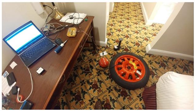
I attached the tire valve stem to the pressure transducer with the rubber hose and Schrader valve connector (luckily the air tank and tires and bicycles all use the same connector).
The pressure transducer is supposed to vary its voltage output from 0.5 to 4.5V between 0 and 100Psi. To covert the read voltage to Psi I used the following simple formula:
PSI = (Voltage — .5) * 25
The ADC is supposed to provide number between 0 and 1024 for 0 to 3.3V but the pressure transducer is 5V. Experimenting with different tire pressures (which meant bleeding pressure and then pumping the tire back up numerous times — good exercise) I arrived at a 3.05 ADC multiplier. Testing over the range of 0 to 30Psi it seemed to get proper and consistent values.
Installation
It was a rainy day in San Jose on November 30 — in fact it was pouring. This is important because in our haste to get the system wired up I soldered the pressure transducer leads to the 22AWG wires and wrapped them in electrical tape. The IoT Sensor was strapped to a pole on near the boiler, the pressure transducer was connected to the air pressure tank and the power supply plugged into an outdoor extension cord. I watched the web page for the sensor data. The system came to life, connected to the WiFi network, sent a start message and started sending pressure readings to the server. We buttoned everything up, tie wrapped the lead wires and ran inside for cover. The IoT sensor continued to send data on schedule. Later though we noticed some anomalies. It appeared that the water dripping down the wires caused erratic readings from the ADC. Rather than soldering we should have used water tight connectors but we didn’t have them at the time. This was corrected later, but water would still be our nemesis.
Operations
We ran the system from November 30 9:02am until March 1 4:01pm. During that time we captured 23328 pressure readings and alerted high/low reading 43 times. It is not yet completely clear if these alerts and the air tank pressure was the “canary in the mine” data necessary to alert of a real boiler problem, but it did provide the maintenance some insight and a better opportunity to be proactive before receiving a call from employees.

Lessons Learned
Re-programmable Firmware
The firmware on the IoT sensor was not over the air re-programmable. This would have useful when we realized that the IoT sensor was alerting too rapidly when the pressure was high or low. We were able to deal with the excessive messages on the server side and build in some “hold down” to that SMS messages were sent at a much lower interval. This did mean that many unnecessary messages were being sent to the server. Since the system was using WiFi and the data was just 41 bytes with 130 bytes overhead the total excess messages and data over the 3 months was just over 100K. If this were on a low power constrained network this could have been a problem, but on a high speed WiFi network this data was in the noise.
Proper Sealing — wires and case
As mentioned using soldered wires with electrical wrapping was not a good choice in an outdoor environment. But just as important is properly sealing the ingress points to the case for the MCU (or maybe a drain hole. We thought that since the case was strapped to a pole under a cover that it would be shielded enough from the elements. This was only partially true. It seems that water did make its way into the case and very nearly filled the case — the MCU board was treading water. Interestingly this did NOT short out the board or the USB power supply, but it did cause the board to only read a pressure of 63.8Psi.
Rubber tubing in the California sun
After just a few months in the sun and rain the rubber pressure tubing connecting the pressure transducer to the air pressure tank became cracked and brittle. This is NOT a good long term solution and proper metal fittings would server better.
End of Story
On March 1 at approximately 4pm we shutdown the Boiler sensor. We still need to analyze all of the data and see if the reading did provide useful information for predictive maintenance. We will investigate rebuilding the sensor with better sealing of the case and wires and a better connection to the air pressure tank and look at reinstalling, but the project did show:
- We can build a relatively low cost single purpose sensor.
- We can reduce the BOM cost significantly to well under $30
- We can build a simple web server that can capture real time data
- We can build a server that will forward alerts to SMS
- We can make the installation very nearly plug and play
- We can build a simple data visualization tool
- We can provide information to support personnel
- We can use the same design and platform to provide other types of sensor data — temp, humidity, light, vibration, …